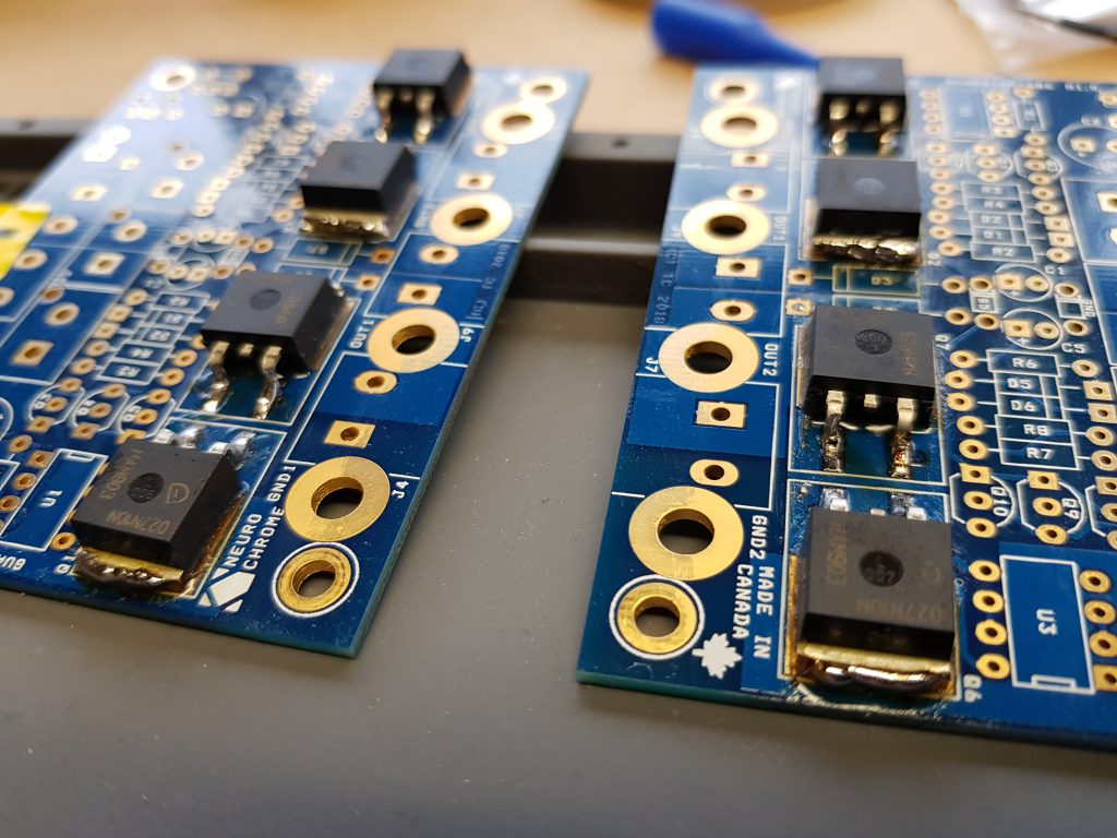
If you are a novice builder like myself then at this point it might be a good idea to test the signal path to save re-soldering when the other components are installed. Test continuity with a multi-meter between:
J2 (Pin 1) -> Q1 (Center Pin/Tab)
Q2 (Center Pin/Tab) -> Out1
J2 (Pin 2) -> Q6 (Center Pin/Tab)
Q7 (Center Pin/Tab) -> Out2
After mounting and testing the boards had problems, some of the transistors lost connectivity and had to be re-soldered.
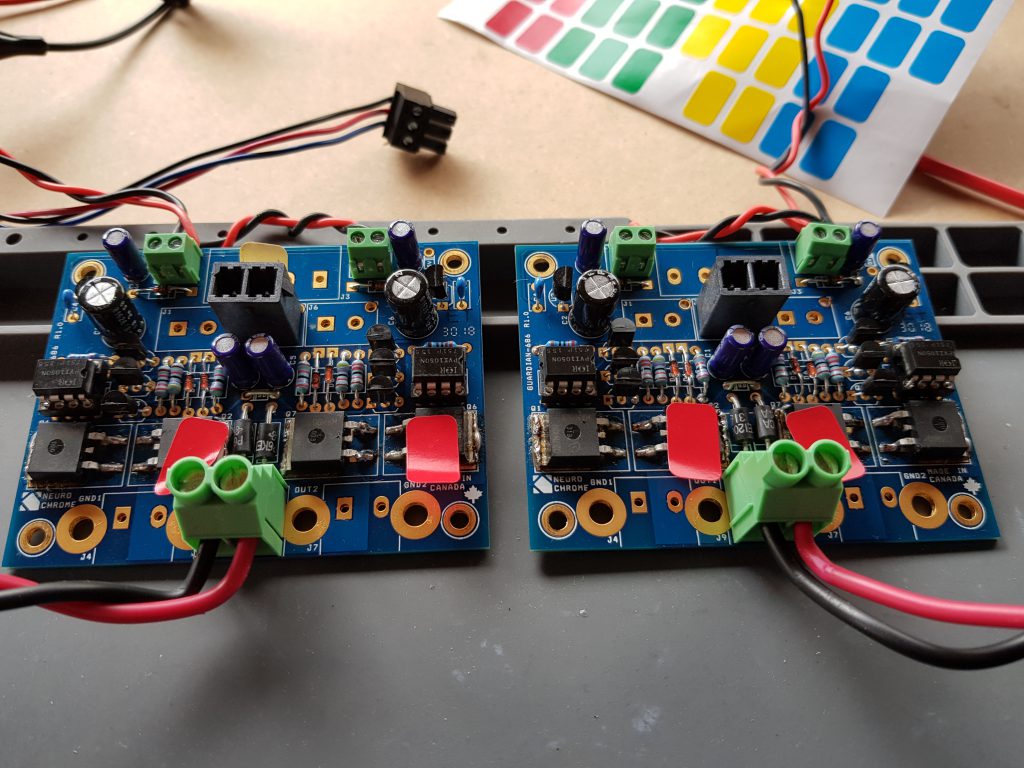
If it happens again, they will be re-soldered whilst on the heat sink.
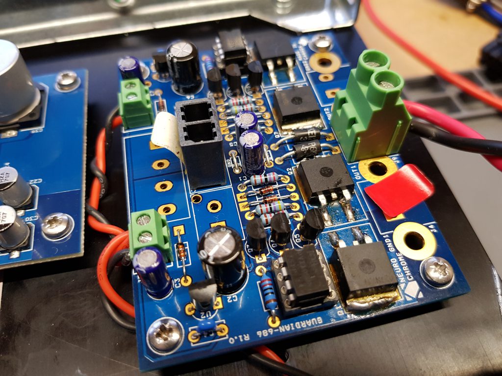
Had to re-solder whilst mounted, having fun.